 InstaMAT Studio supports working with multiple UDIMs in both layer-based and node-based project types. This article demonstrates how to process and texture meshes that have been set up with multiple UDIMs using InstaMAT's Element Graph.
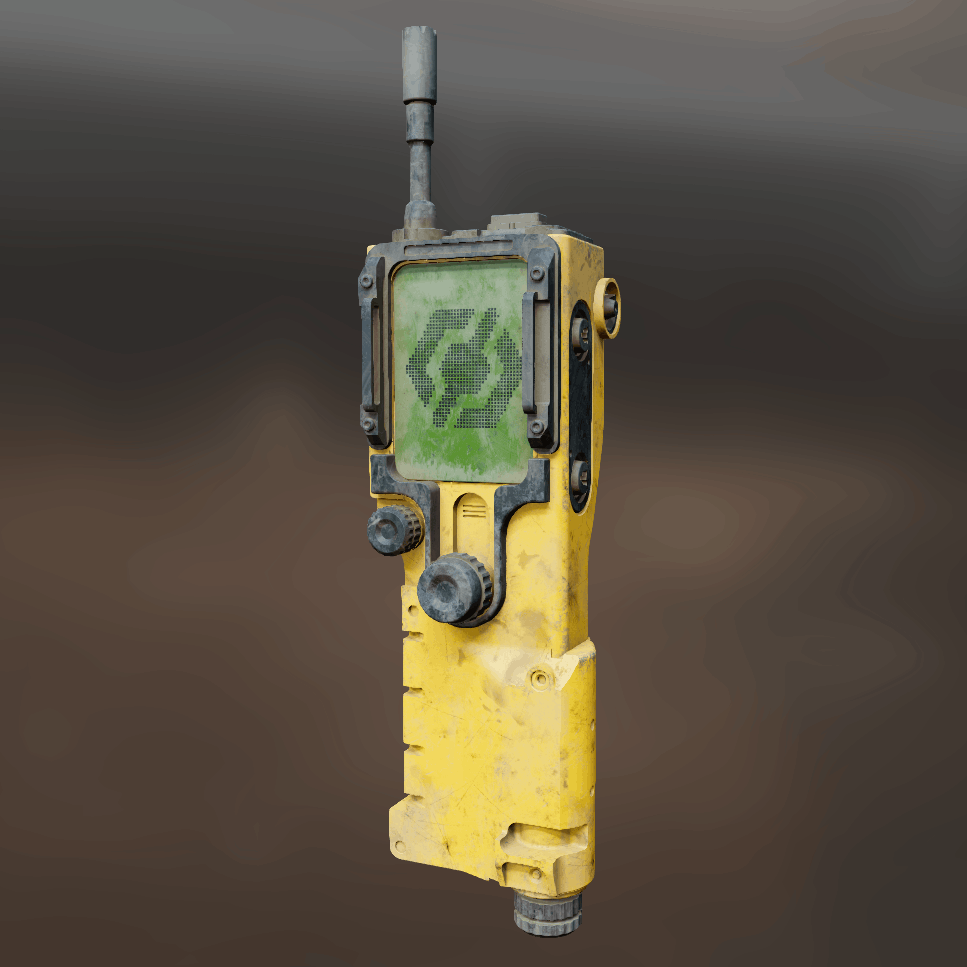
The following illustrates a simple example that utilizes both an Asset Texturing project and nodes in the Canvas to texture a communicator mesh with three UDIM tiles.
There are three main concepts to understand when working with UDIMs in Canvas:
- Meshes set up for UDIMs must be preprocessed with the
Mesh UDIM Preprocessnode. - After preprocessing, each UDIM is represented as a material section with a name that corresponds with the UDIM number such as "udim_1001".
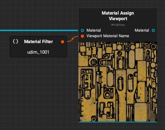
- To view multiple UDIMs in the 3D viewport, a
Material Assign Viewportnode can be used for each UDIM tile with theViewport Material Nameparameter set to a corresponding tile name ex: "udim_1001".
¶ Preprocessing
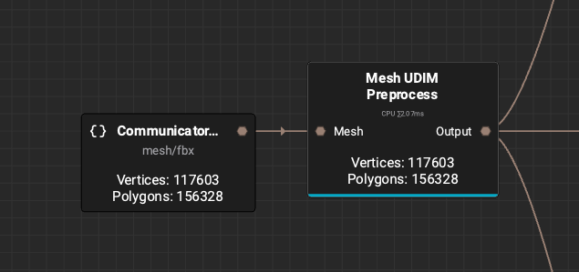
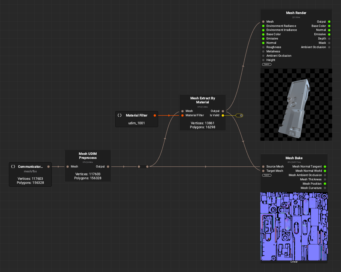
In order to work with a mesh set up for multiple UDIMs, it must first be preprocessed with the Mesh UDIM Preprocess node. This will set up the mesh so that each UDIM tile can be accessed as a material section with a name that corresponds to the UDIM tile. For example: "udim_1001".
¶ Extracting and Baking
Once the mesh has been preprocessed, each tile's meshes can be extracted so that mesh maps can be baked for use when texturing. This can be accomplished by using the Mesh Extract by Material node and using the UDIM number for the Mesh Filter parameter. In this case, "udim_1001".
The extracted meshes can then be baked using the Mesh Bake node with the preprocessed mesh as the Source Mesh and the extracted mesh as the Target Mesh.
In this example, a
Mesh Rendernode is use to illustrate the extraction process and to visualize which parts of the mesh are associated with this UDIM tile.
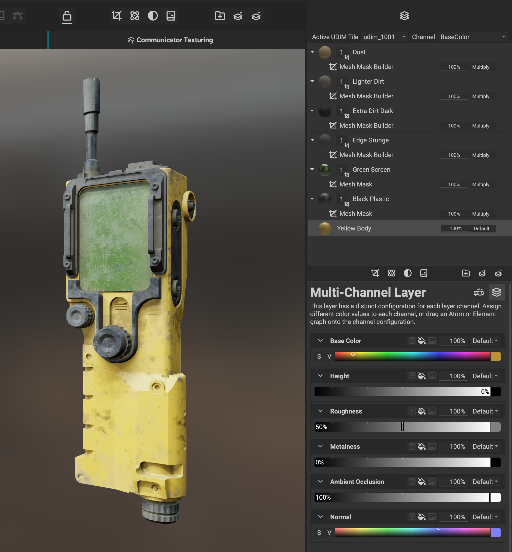
¶ Texturing with an Asset Texturing Project
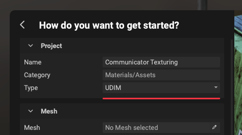 With InstaMAT Studio it is possible to integrate layer-based Asset Texturing projects with node-based projects in the
 Canvas simply by dragging them from the Package Management panel into the graph. The following Asset Texturing project was created with UDIM set as the project Type during its creation.
To learn more about InstaMAT project integration, please read our dedicated article here.
The following illustrates the layering project setup for texturing a majority of the communicator asset.
After dragging the layering project into the graph, connect the baked mesh maps (known as MeshBakeData when using Link Category mode) from the Mesh Bake node to the layering project node. Use the output of the Mesh UDIM Preprocess node as the input for the layering project's Mesh input.
Important: It is important that the layering project receives direct input from the
Mesh UDIM Preprocessnode. The mesh from the preprocess node carries special information to the layering engine which cannot be transferred through other nodes. This includes reroute nodes. Therefore a direct connection must be made.To organize these connections in the graph, double-click a connection to create a temporary reroute point that you can reposition to better arrange the flow.
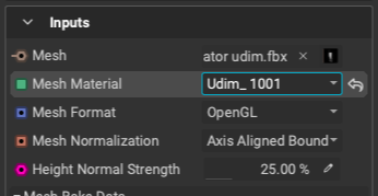
Be sure to select the layering project node and choose the corresponding UDIM tile with the Mesh Material dropdown menu in the Graph Object Editor.
The following illustrates the setup so far using a Mesh Render node to visualize the extracted meshes with textures applied from the layering project.
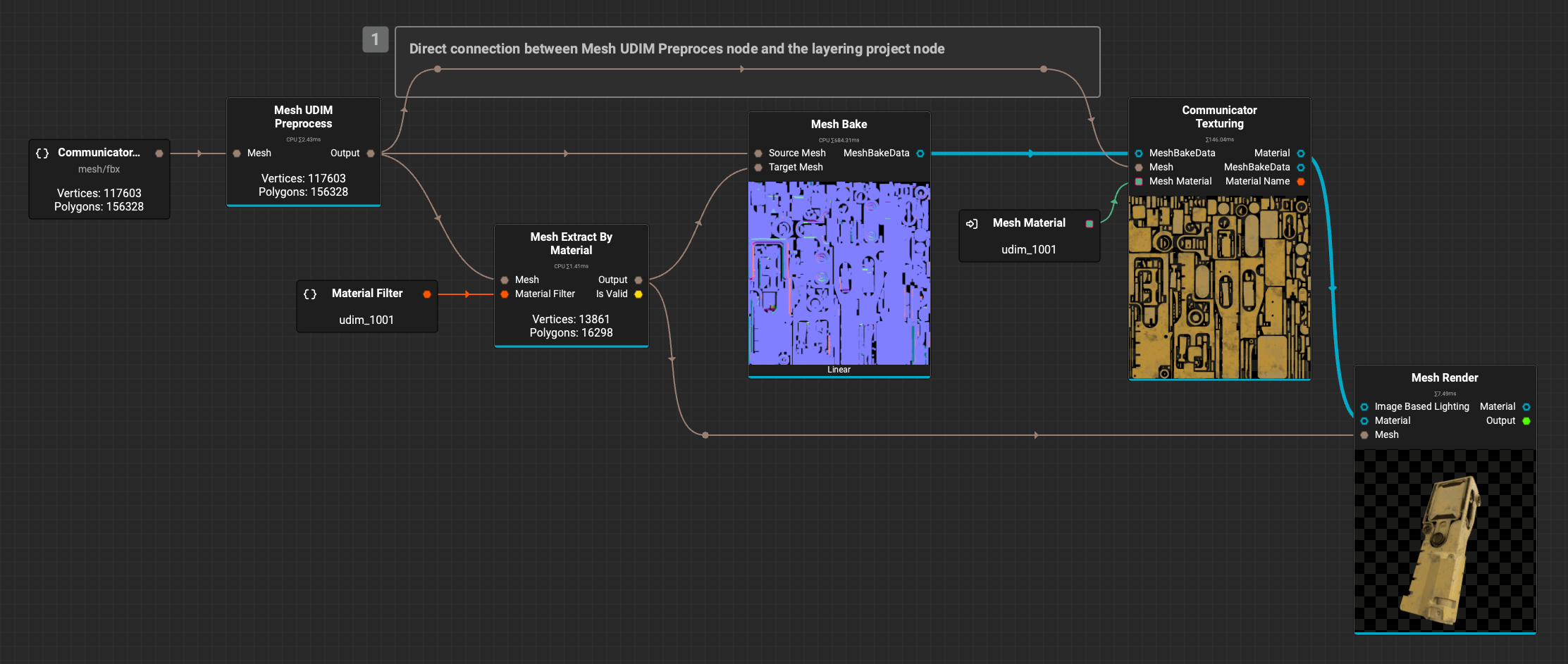
The above screenshot demonstrates
Link Category Mode, which combines related connections into one, making it easier to connect multiple channels of data. This is denoted by the blue connection line. To enableLink Category Mode, click the icon in the main toolbar.
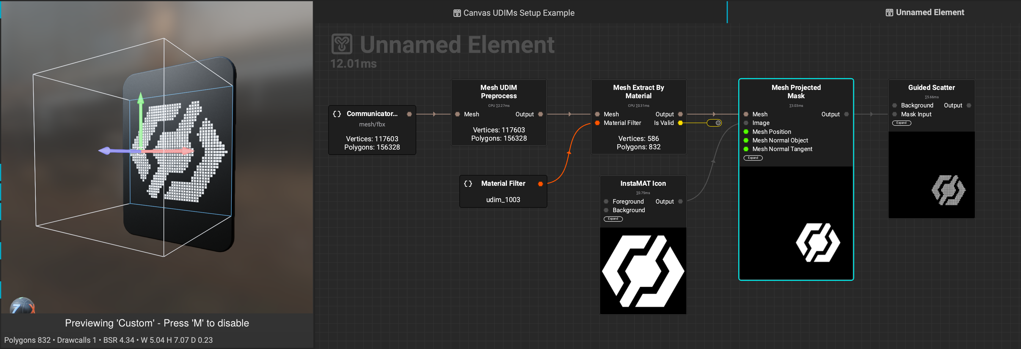
¶ Texturing with Nodes in the Canvas
UDIM tiles can be textured using nodes in the Canvas directly. This example demonstrates texturing the screen of the communicator by extracting the meshes belonging to "udim_1003" and applying an LCD screen effect using the Mesh Projected Mask and Guided Scatter nodes.
In this case, the Mesh Projected Mask has its Projection Mode set to Decal making it easy to position the InstaMAT logo using the viewport gizmos.
¶ Displaying Multiple UDIM Tiles in the Viewport
 To view multiple textured UDIM tiles in the 3D viewport:
- View the output of the
Mesh UDIM Preprocessnode by clicking on its output pin, or right-clicking the node and selectingView Mesh 'Output'from the contextual menu. - Create a
Material Assign Viewportnode for every UDIM tile and set theViewport Material Nameparameter to its corresponding UDIM tile number. For example: "udim_1001".
¶ Complete Example
The following graph demonstrates the full process for preprocessing, texturing, and visualizing the communicator mesh with three UDIM tiles.
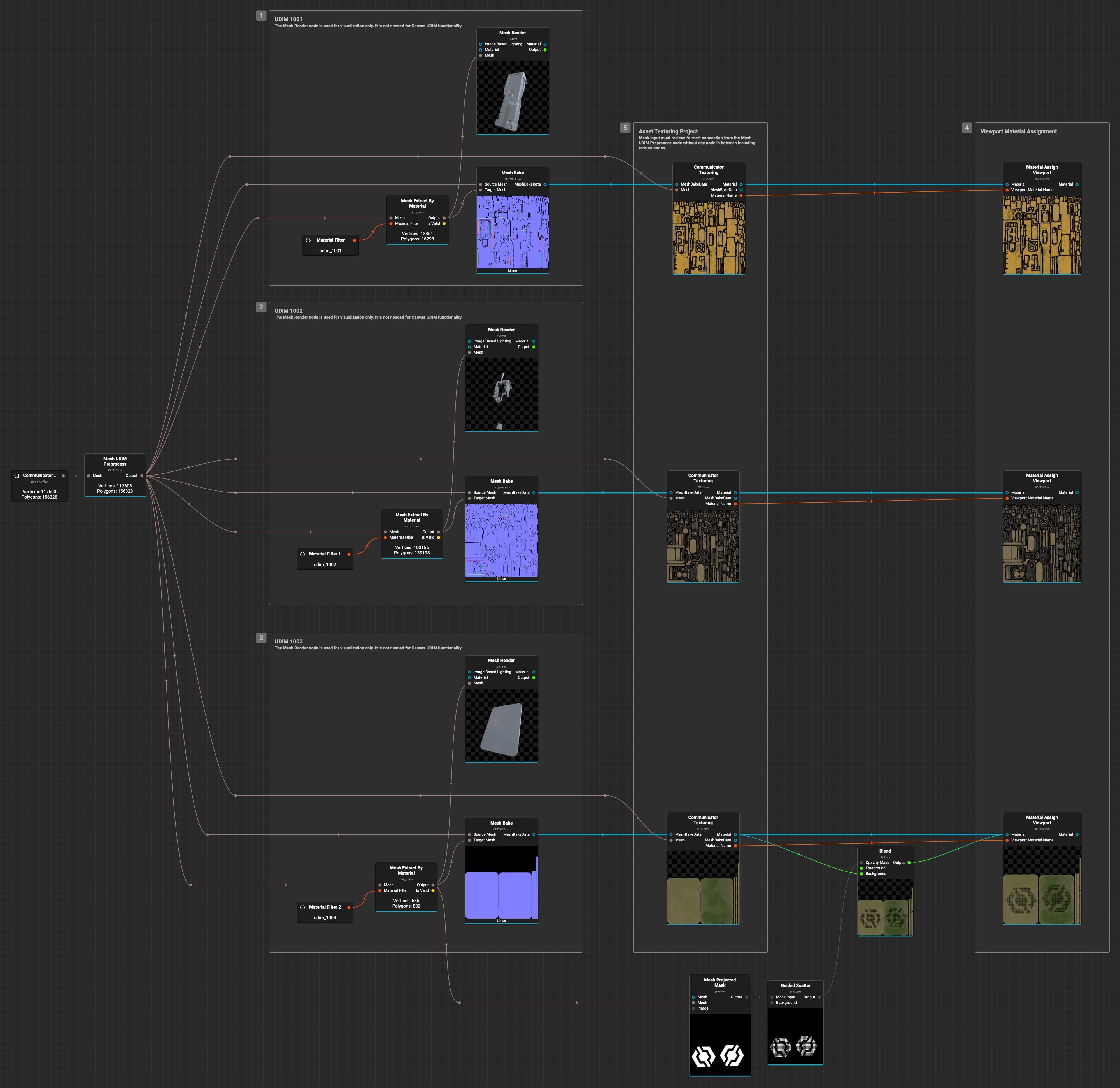
Right-click the image to view it in a separate window or tab to zoom in and see the finer details.